Custom 3d Printer Enclosure
I created this 3d printer enclosure so that I could test my programming skills and also print ABS on my 3d printer. Since ABS are highly toxic and it is prone to warping when printing, an enclosure with filtration or exhaust is necessary.
The challenge I set for myself here was to use my 3d printer to create the enclosure. I couldn’t create things like the frame or plexiglass and insulation, but I could create all the brackets using brackets that I designed and 3d printed. Additionally, I wanted it to be controlled via a PID setup.

Controlling Temperature with Arduino
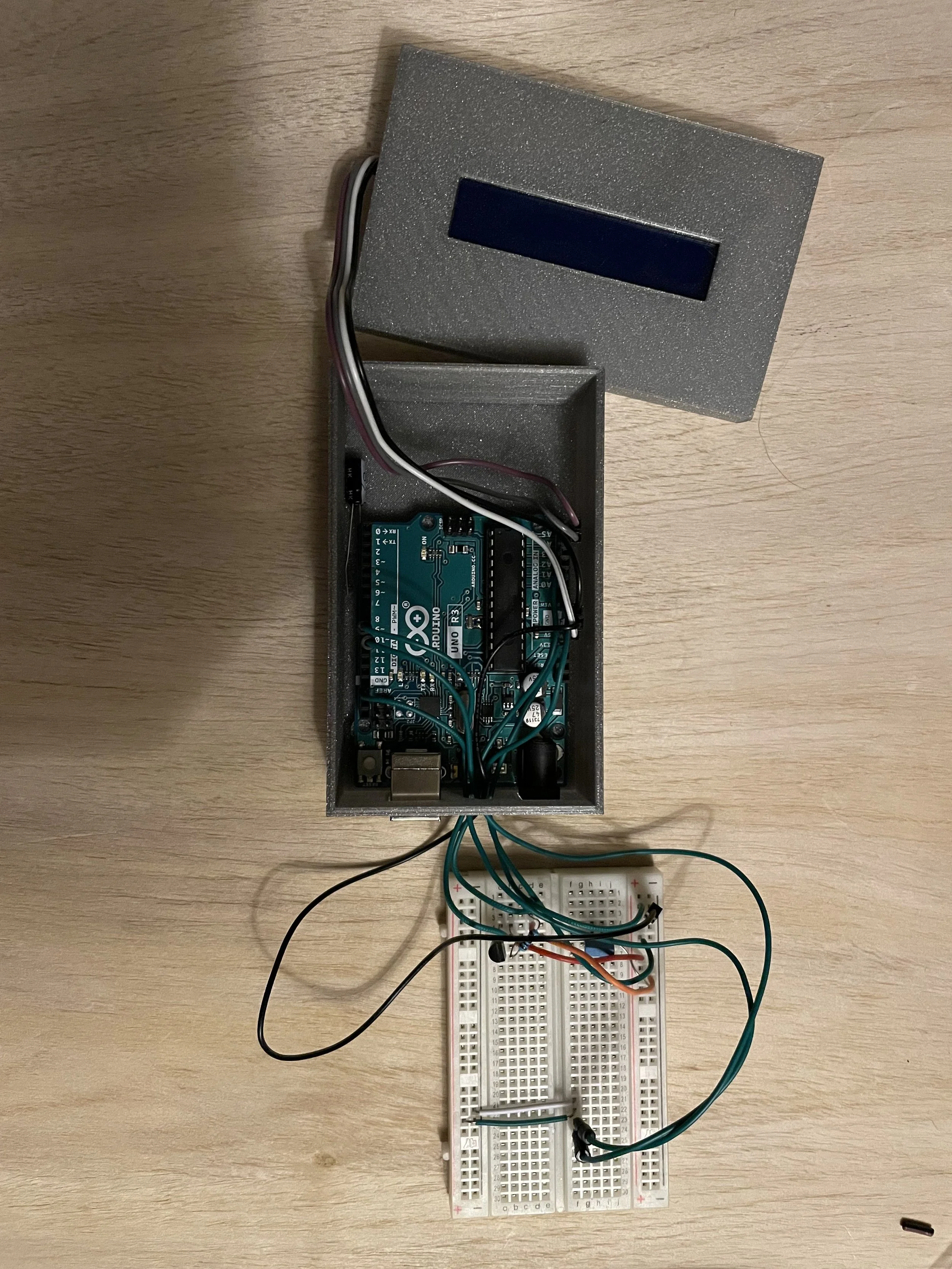
The heart of the enclosure lies in its program. In this case I used an Arduino Uno to create a PID fan controller. It would take input from a DS18B20 temperature sensor and adjust its fan speed in order to meet that temperature goal. The reason we need temperature control is because Prusa does not recommend letting the stepper motors on a Prusa Mk3s get above 40 degrees Celsius.
Writing the program was difficult. At first I was using an analog temperature sensor and the noise on it caused all different types of temperature values to be produced. To mitigate this, I created a section of code that would collect the running average, therefore it didn’t spike suddenly, which would drive the fan to 100% power on and off. The other issue this created however was that the sensor itself would drift overtime. As a result I moved away from an analog sensor and used a digital sensor instead.
The sensor I used was a DS18B20 temperature sensor. The nice thing about this sensor is that you can run multiple sensors, but only read off of one digital input. This works because it stores each of the sensors values in an index. This is perfect for my use case because having multiple sensors means I could place them at different locations in the chamber and control my fan based off of the warmest one.
The next challenge I faced with my program was controlling the fan speed. Because I was using an old computer case fan, my fan didn’t support 0 PWM. A fan that supports 0 PWM could be set to a value of 0 and then turn off. In this case if you set the PWM value to 0, it would just run the fan at full speed. To correct this, I set my output limits for my PID function from 20 to 255. This also worked well because I wanted to create a negative air pressure environment inside of my 3d printer case. This meant that no matter what, fumes would not escape from the small gaps in the enclosure and instead air inside the room would be drawn in towards the enclosure.
Venting and Flow Through a Packed Bed
My inital design involved an air scrubber made of a combination of an activated carbon and HEPA filter. The challenge with this became very apparent, very quickly. A standard case fan for a computer does not have the static pressure capabilities to push through a packed bed of filtration media.
I started off by calculating a necessary amount of carbon that would be required to filter out a typical ABS print. To do this, I used PrusaSlicer to get an estimate of how much filament I would use for a print in meters. Then I used the total length of the spool divided by its weight to get a mass per linear foot. I then matter of looked up the molecular weights of the pollutants of ABS and what percentage of each was present. This allowed me to then use the EPA’s rule for working capacity of 10-20 pounds of contaminants per 100 lbs of activated carbon. I translated this into volume of activated carbon by weighing out the correct amount of activated carbon in a known volume. This assumed I would filter every contaminant in one pass through the filter.
The next issue I faced was no air flow through my filter. I first started by removing the HEPA filter from the equation. With the HEPA filter from the equation I still felt a lack of air flow. I started doing some research and discovered Ergun’s equation for flow through a packed bed. I then used Matlab to calculate the pressure loss across the packed bed of activated charcoal cylinders. Matlab allowed me to play with different surface areas of filtration without spending too much time. After playing with the geometry and trying to reduce the amount of surface area of activated carbon while maintaining the correct volume, I realized it wouldn’t be possible with the equipment I had. Other filters on the hobby market require recirculation, and I think this is because you would need a very high pressure fan in order to effectively pass the air through the filtration media.
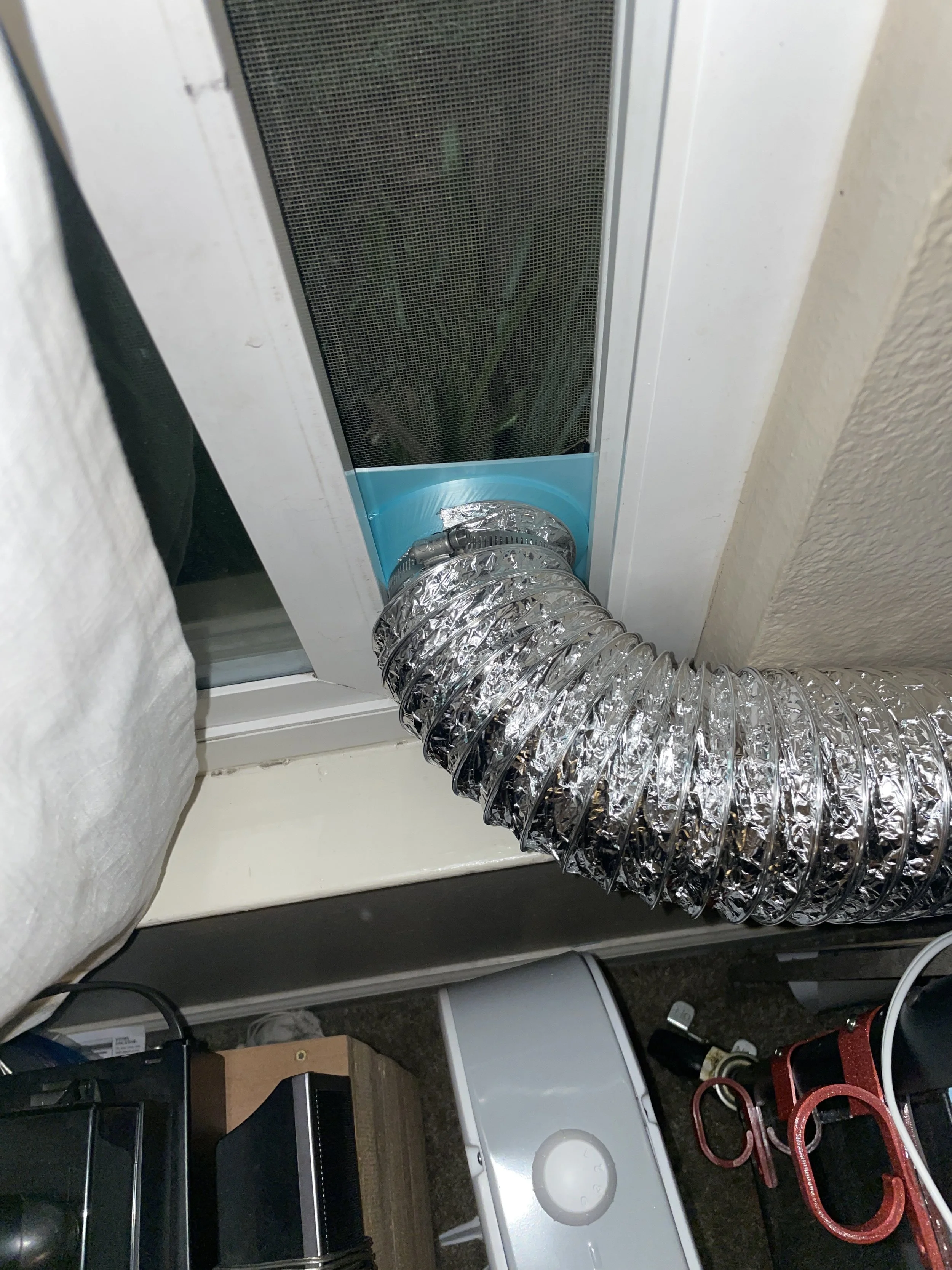
I opted for a simpler idea instead, which was to run an exhaust tube from the top of the printer and send the fumes outside so no one near the printer would breathe them in.
The Result
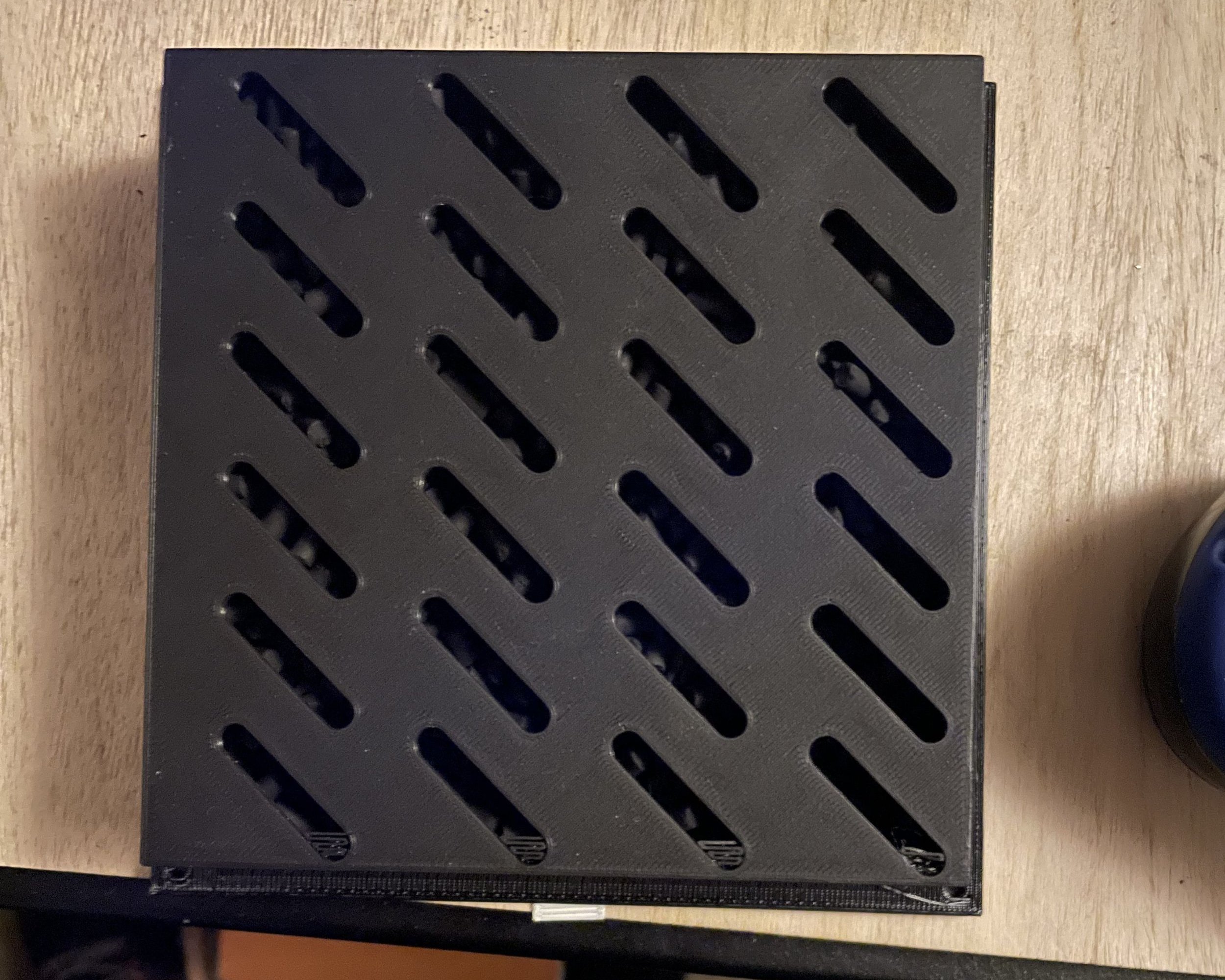
The end result was a 3d printer enclosure that worked as I intended. I had a door that magnetically snapped shut, a place to mount spools of filament, and a controllable temperature inside my enclosure. It worked great for printing ABS and I had no worries about fumes outgassing into the room.