Keyence CL-3000 Fixture Design
At Vacuum Process Engineering, a big push was being made by our upper management team to get better Metrology equipment in. We had a few powerful CMM machines we would use, but we wanted equipment that was easier for our production team to use. It was one of my responsibilities to setup this new equipment and teach our production team how to use it.
The first piece of metrology equipment we purchased was a Keyence CL-3000. We chose this because we wanted to reliably measure the thickness of parts and record the data. Additionally, we could scan a part and get a map of the thickness, capturing up to 10,000 data points if we preferred.
Fixture Design and Manufacturing
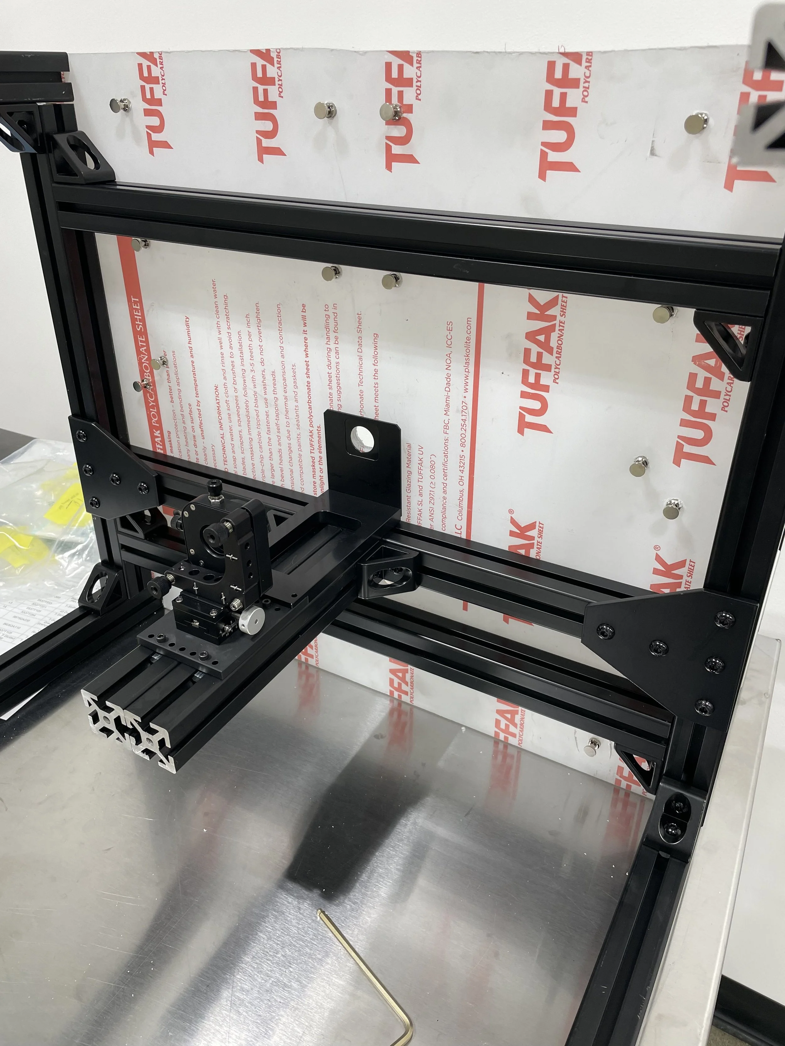
Because we wanted to set up the CL-3000 as fast as possible, I opted to design everything with aluminum extrusions. I chose black anodized extrusions to make it look professional and clean. I designed the fixture using SolidWorks, created drawings for each part, and cut all the pieces myself on our vertical bandsaw.
In this photo I have the fixture laying on it’s back while I install the confocal laser. It’s important that the laser be a certain distance away from the bottom plane of the part you are to measure. For our application we chose the CL-L070 laser head. It has an accuracy range of +/- 2 microns and can measure parts up to 10mm thick, which was perfect for our application. Some of the parts we were measuring had a sintered titanium surface and therefore was difficult to measure with standard micrometers. The CL-3000 has a spot diameter of 500 microns but each spot is actually a collection of 4 points, making this a much more effective tool for us.
I used sheet metal lock pins to create indexable features in the table top and labeled each one based off of their measurement position. This way the measurement of the parts would be repeatable no matter which technician was doing the measurements.
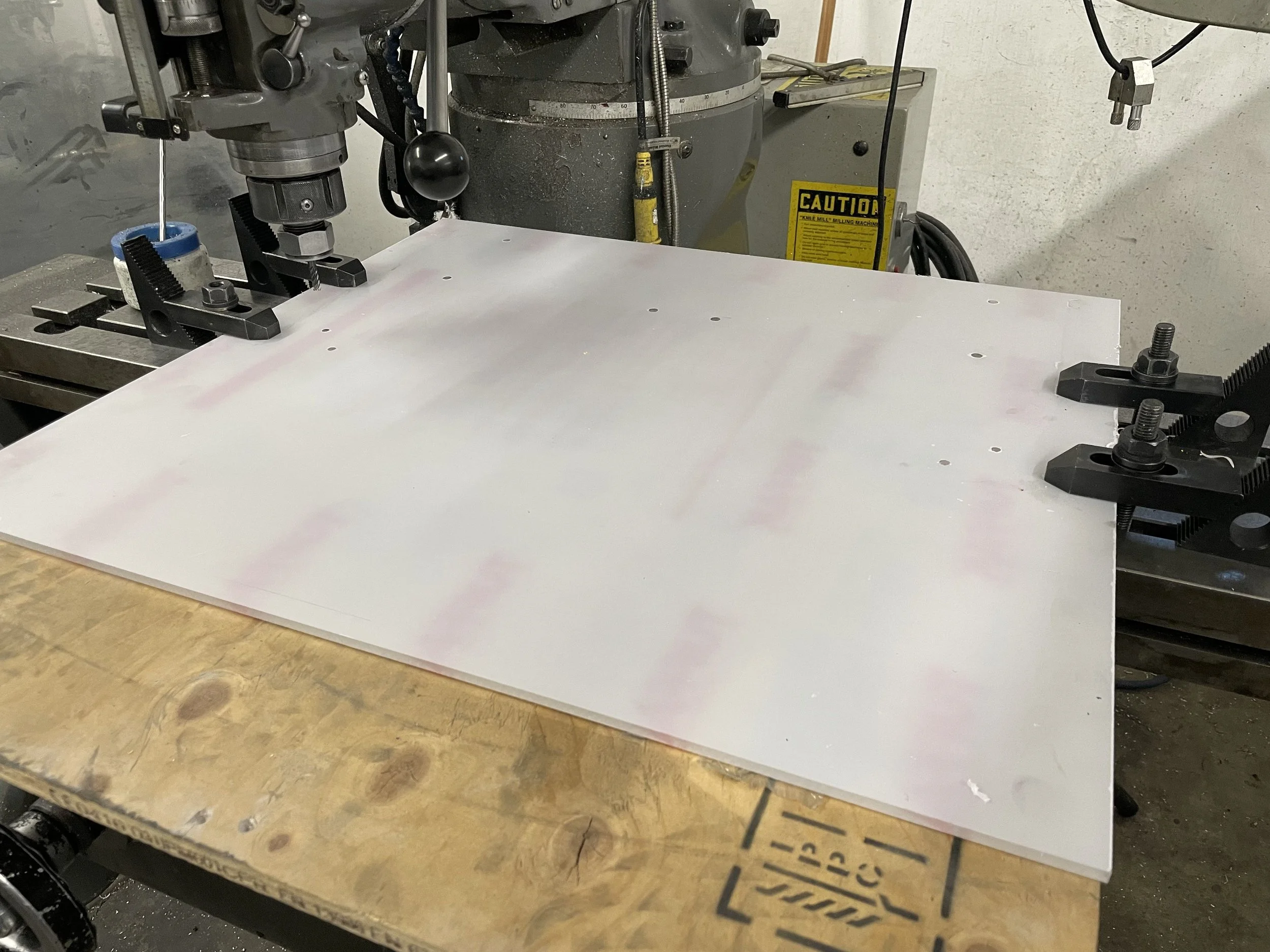
To cut the indexing features in the table top I used the Bridgeport mill. Before I could begin doing this, I had to tram the head of the mill, otherwise my holes would have been crooked. I swept the table using a +/- .0005” dial indicator. I found that the table was high on the left side by about .200”.
After tramming the head I was ready to proceed with making my table top. I removed the vice from table and put a piece of plywood down underneath the plastic so that I would not damage the table. I first created a drawing detailing the hole pattern. I then squared up the back of the plexiglass using a dial indicator, and plunge cut each hole with an endmill.
Installion and Calibration
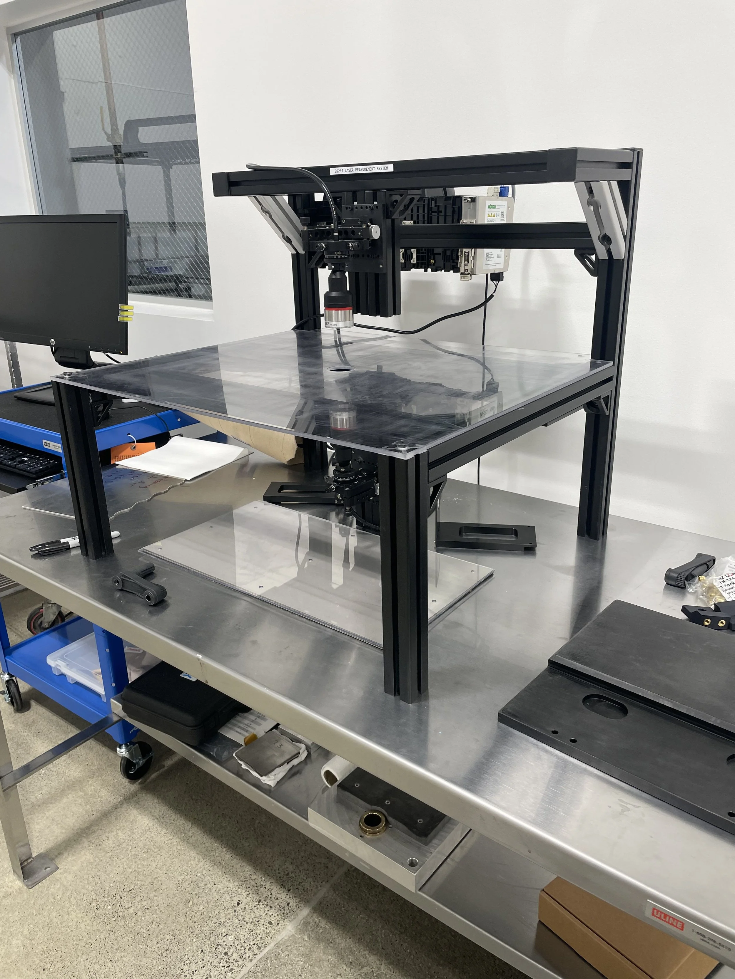
After installing the table top, the next steps were to install the electronics and to calibrate the laser.
For the electronics, everything was provided by Keyence except for a power supply and DIN Rail. I sourced the DIN rail from McMaster Carr and a power supply from Industrial Automation. From my employment at Advanced Farm, we used a lot of Wago products so I had some idea of where to look. I wired everything up myself and was able to get it to communicate with the software. And important part of installing the table was that the bottom laser be exactly 70mm away from the top of the table top. This was something that took me awhile to figure out since Keyence’s documentation wasn’t very clear on that.
I followed the instructions in the Keyence software to calibrate the laser. It was measuring in the .0000x” range, and as a result was very unstable. To remedy this I changed it’s resolution range to tenths of an inch. The great thing about this product is that Keyence says ambient temperature doesn’t affect its measurement. I found this to be the case as well but you do need to re-zero the machine periodically and recheck its calibration.
To calibrate the laser, the software asks that we apply a linear correction to the measurement we are initially reading. To begin you take a known object and measure it, in this case I chose a .020” gauge block. It tells you what it’s measurement value it reads and asks that you input what the measurement value is supposed to be. You then do this again for the top value in the range. Because this correction is linear, my intuition told me to not exceed the range of my parts by too much since that would cause inaccuracies. In my case I used a .250” gauge block.
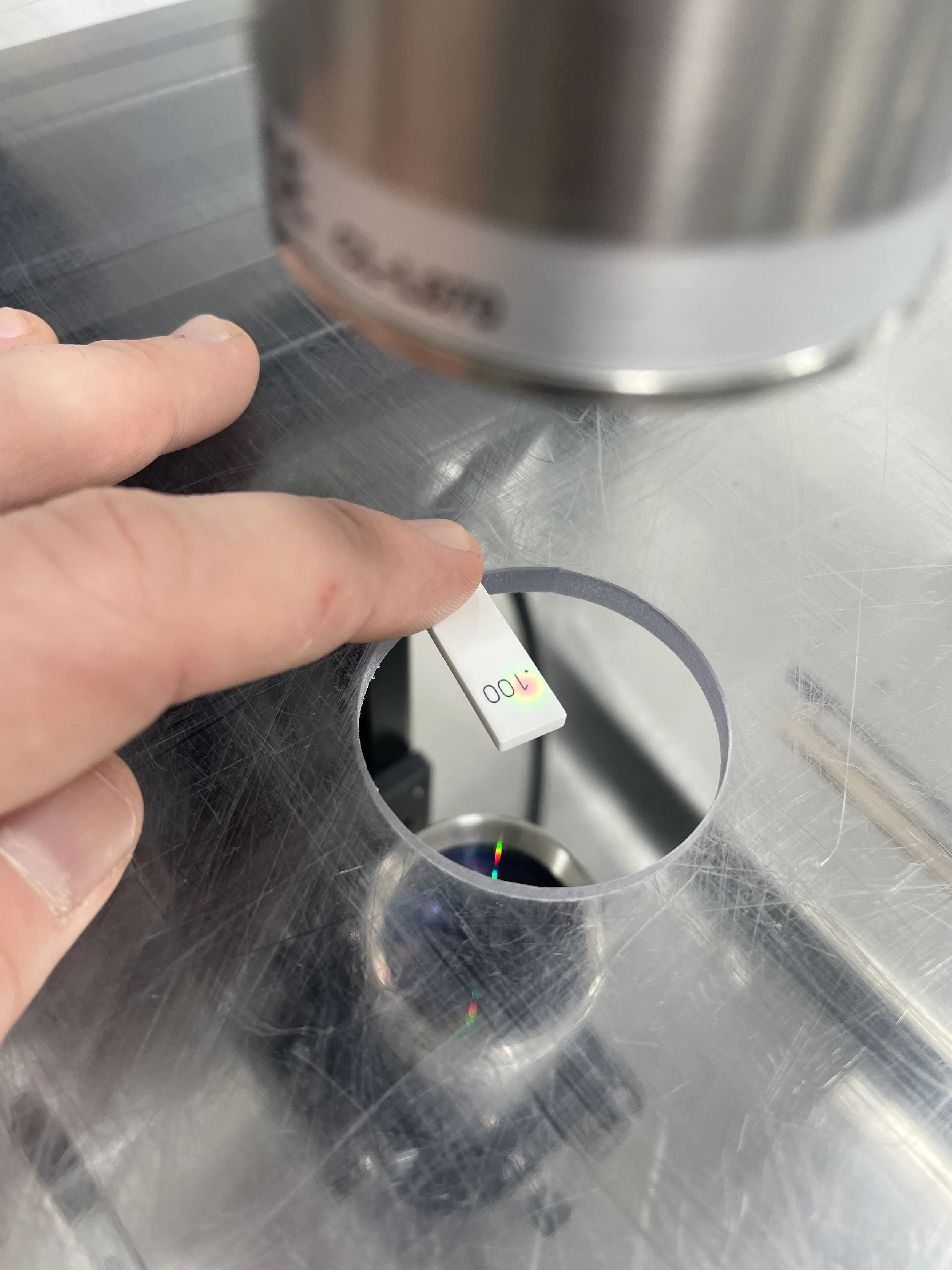
Afterwards I verified the the calibration of the Confocal Laser was verified using a Mitutoyo .100” Grade 00 Ceramic Gauge block.
With this calibrated, we were able to take quick measurement of the thickness of parts and export the data as CSV files to be used an analyzed in Excel.