Jeep Gladiator - Rear Sway Bar Reinforcement Bracket
This project came about due to being a Design Engineer at MetalCloak. Our Production Manager had an issue where he damaged the bracket holding his rear sway bar to frame.
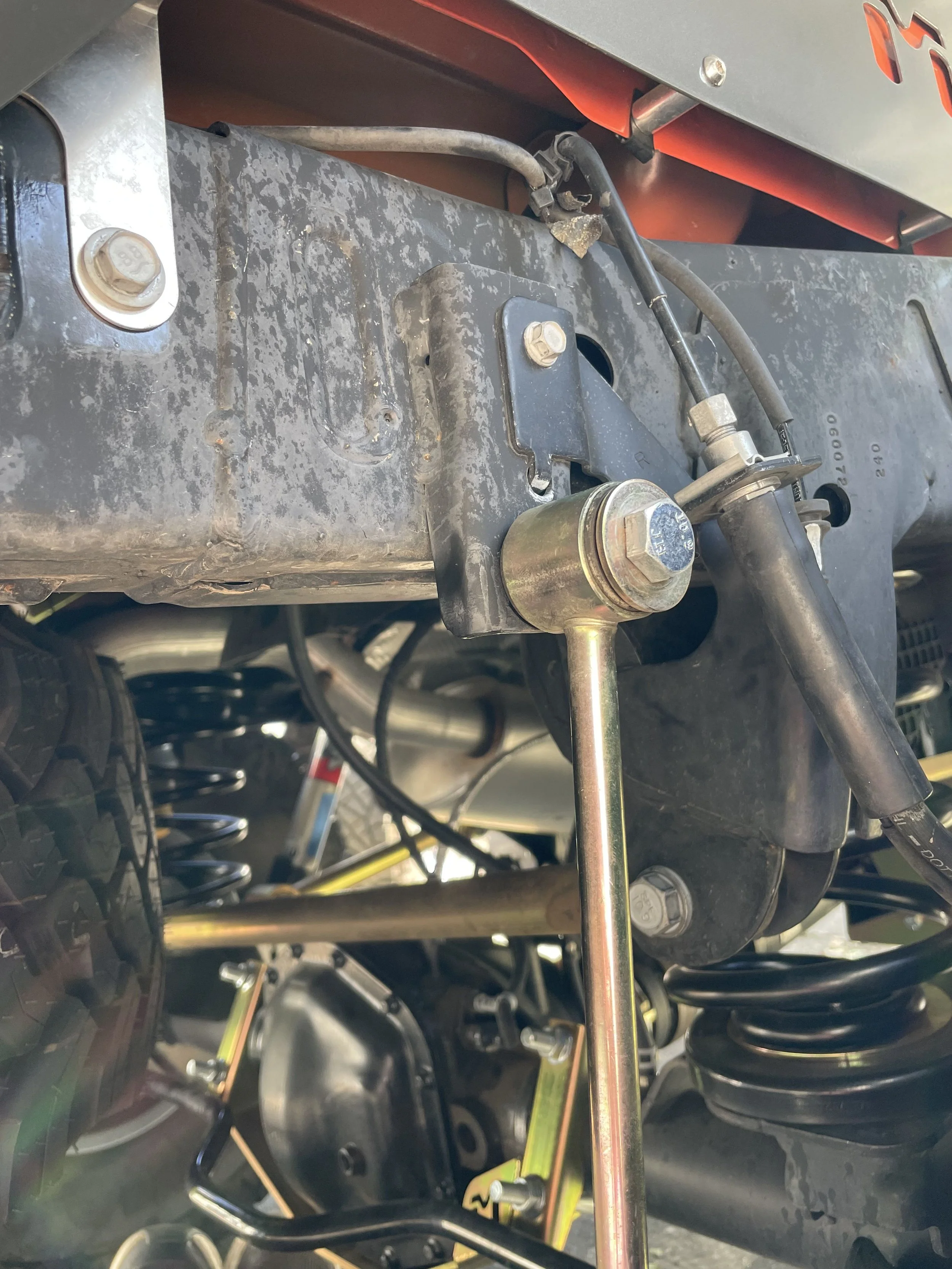
Original Damage and Design Idea
On the right is an image of the original bracket. The damage our production manager experienced was that the lower half of the bracket completely sheared off when he landed on a rock. This was caused by the sway bar bending under the weight of the jeep, effectively tearing out the bolt from the lower half of the bracket. The lower portion of the sway bar sits center with the back of the wheels.
My first objective was to determine what kind of repair needed to be done, and if that repair was marketable. Me and my coworker played with the idea of either welding on a new bracket or creating something bolt on. To better ascertain what was the better approach, I started by looking up the FCA guidelines for body repair on a Jeep Gladiator. FCA recommends that you don’t weld any part of the frame, and if you have to, to weld lengthwise along the frame as to reduce the effect of welding on the cross sectional area of the frame.
This told me two things, one that a weldable bracket would be difficult and might damage the frame of a customer’s Jeep, and two that the frame was some type of heat treated steel.
I used this second assumption to calculate what I suspected was a tear out failure mode of the bracket. To do this, I looked through the Machinery’s Handbook and found a steel commonly used in heat treated applications but with a lower carbon content and calculated the amount of tear out the bracket could withstand. I ended up with about 7,000lbs of force. This made sense to me because the whole weight of the Jeep came down on one singular member and a Jeep with custom suspension and skid plates end up weighing about that much.
The next thing was to figure what steel we commonly used in house and if it would work. I ended up using Mild Steel plate that was 1/4” thick. After doing the tear out calculation on that material, I ended up getting an allowable force of about 13,500lbs. For this calculation I considered the endurance limit with a factor of safety of 1.5 as the final allowable force, so that I could take into account the stress cycles that it would experience.

Prototyping and Fit Checking
After coming up with an idea for design, it was time to get to work fit checking and creating prototypes.
This was the first prototype I came up with. Because of the no weld rule I set for myself, I found 2 bolt holes on the jeep frame that could be purposed for my bracket. I had to avoid the brake line bracket of the rear sway bar mounting position and decided to wrap it around the bottom. It also gave me an opportunity to add our MetalCloak logo to it.
The issue with this design was just simply how low it hanged and it didn’t look quite as good as it could. Because our bending machine needs parallel edges to create an accurate bend, I thought making it more square like this would have to be the approach.

Final Design
The final design incorporated a different bending technique that my coworker thought of and he was the one to give the part its final shape. The MetalCloak logo was reduced and more material was added to the top of the bracket so it could resist even more bending stress applied to it.
Overall this is a product I’m very proud of and every once in awhile I go back to the MetalCloak website to read the reviews and love seeing people enjoy this product I designed.