CO2 Laser Repair and Calibration
This project was a result of me diagnosing issues during my Polyimide Film Lamination project. The problem I noticed was that ever since they switched out our CO2 laser cutter, the rectangles I was cutting were more like parallelograms. This told me that the X and Y rails were out of tram.
Fixing Tram
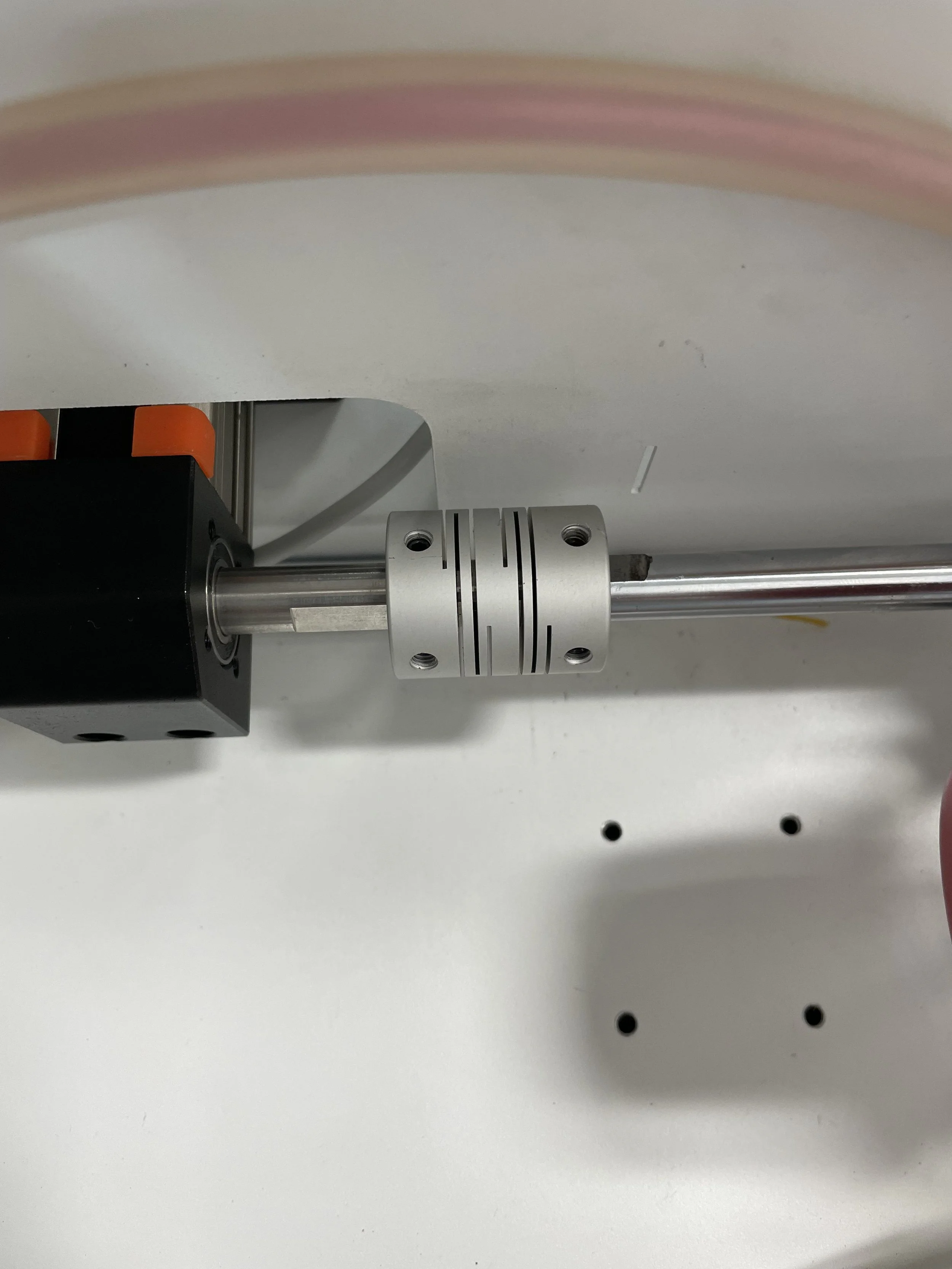
II identified the out of tram condition being caused by the flex shaft set screws backing out. This caused a mismatch in rotation between the drive side of the Y-axis and the flex shaft side of the Y-axis.
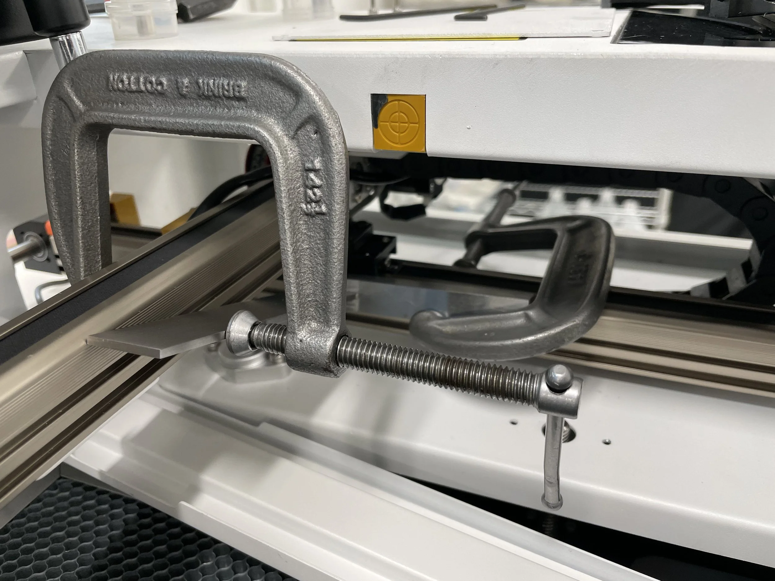
First I loosened up the flexible coupler all the way and removed it, allowing the right hand Y-axis to move freely. I brought a machinist’s square from home and used it to pin the X and Y axis with some small C clamps. This would force the axes into square by an amount that equaled the tolerance of my machinist square. In this case, my machinist square has a perpendicularity tolerance of .0006”.
Then I went back and tightened the flex coupler, first on the shaft side then on the opposite side.
Realigning the Mirrors
After all of my adjustments with the axes and removing of the laser tube, I quickly realized I had bumped something in the process and the mirrors would need to be realigned.
Starting at mirror 1, I noticed the laser was hitting too low in the target and not center. I corrected this by using some precision stainless steel shims which we use for leveling furnaces.
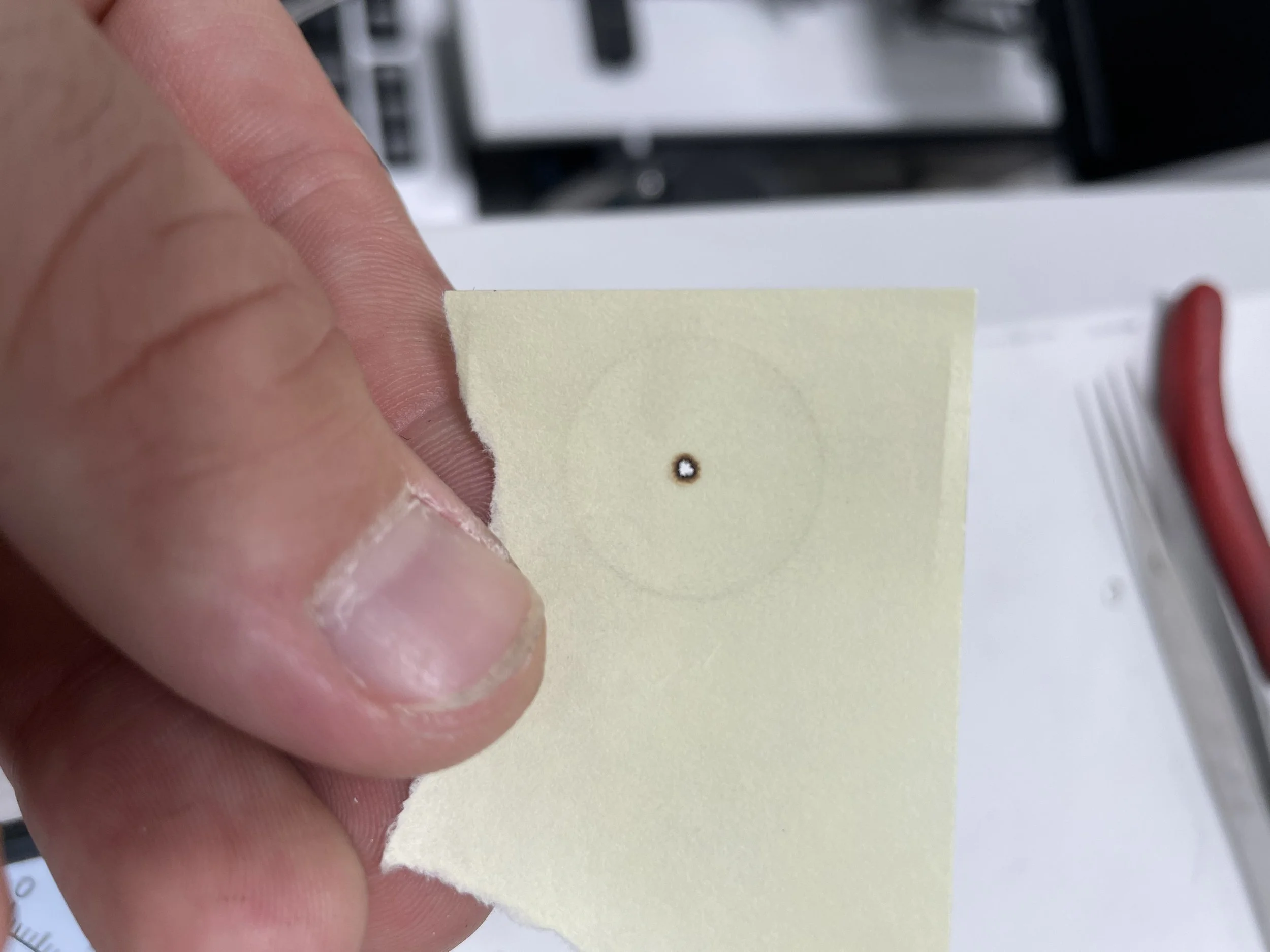
After that I began the process of adjusting the 1st, 2nd and 3rd mirrors. To adjust the 1st mirror, I started by putting a sticky note on the 2nd mirror and moving it to its furthest position. I then pulsed the laser to get a burn mark. Afterwards I brought it forward all the way and produced another burn mark. At this point it then becomes a matter of making the spots coalesce by adjusting the mirror via its adjustment knobs. One knob moves the mirror diagonally, another vertically, and another horizontally. In my case I had to adjust all 3 since it was so bad.
I repeated this for the 2nd mirror and then the 3rd mirror to get a uniform beam leaving the 3rd and final mirror.
Adjusting Table Height and Metrology
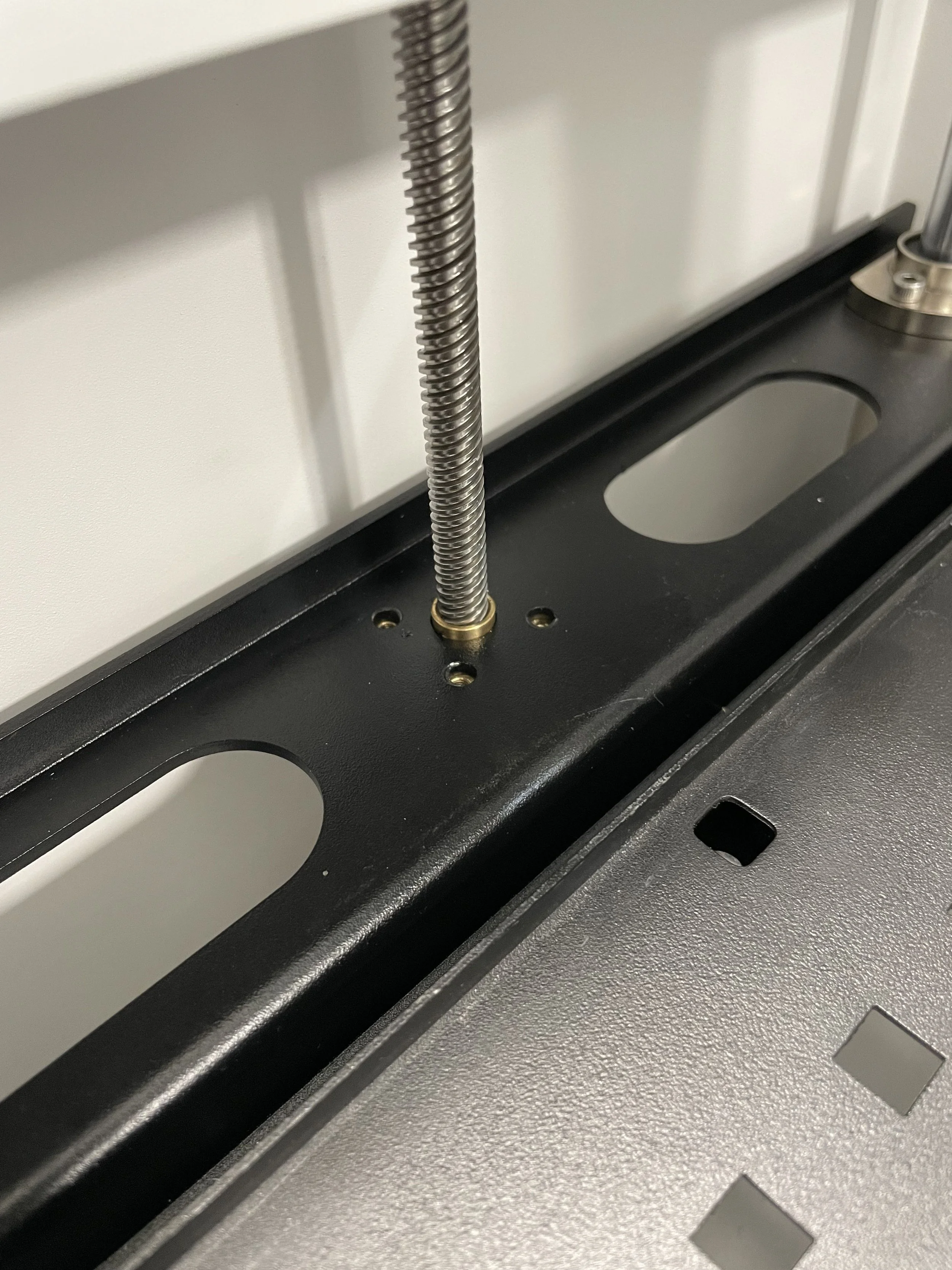
Despite adjusting the mirrors, I was still noticing an inconsistency in cutting on one side of the table. I noticed the table had a sag on the left and as a result the laser was moving further away from the target, thus creating a larger heat affected zone on the piece being cut. Since this affected the accuracy of the cut it had to be addressed.
To fix this issue, I loosened the screws from the ball screw flange nut and rotated the flange nut a quarter of a turn, driving this side of the table up.
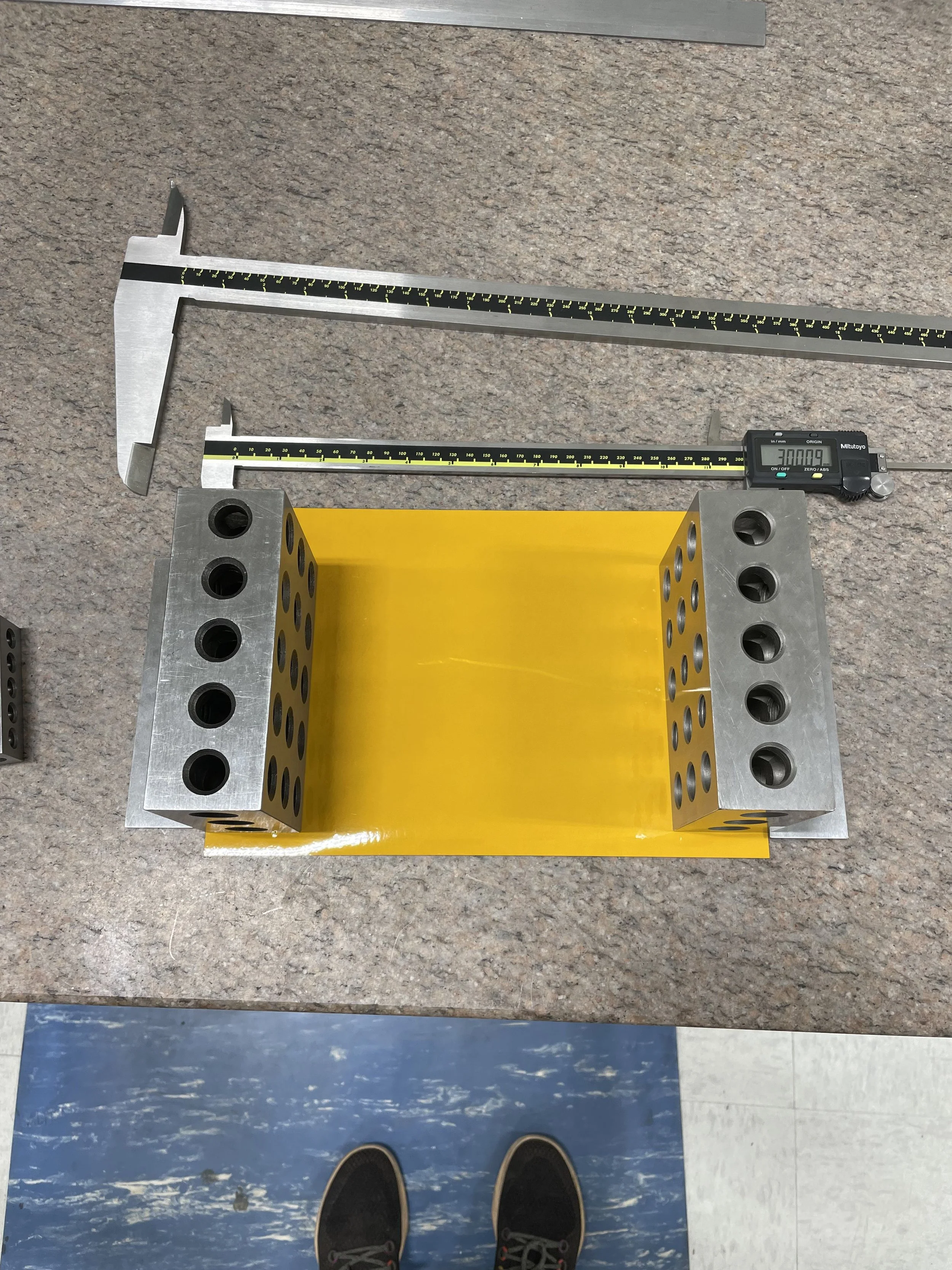
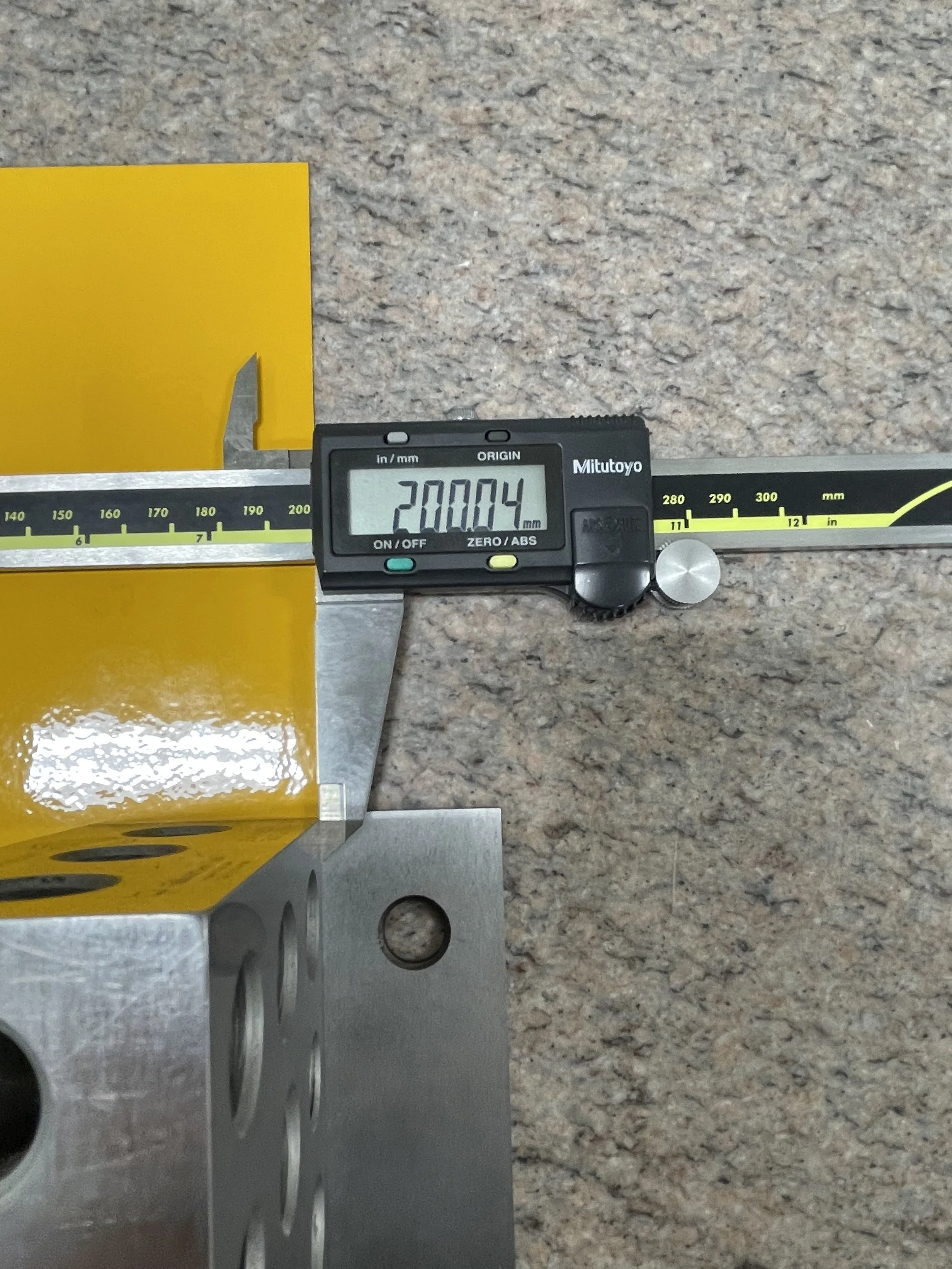
At this point it was just a matter of creating a calibration rectangle and using the software’s calibration function to adjust the steps of the motors. Before I had started this process it was cutting a 200mm x 300mm rectangle to a dimension of 200.77mm x 300.68mm. My setup for measuring is shown on the right. I had a hard time measuring what was essentially a piece of paper so I came up with this idea to measure the outside dimensions. I placed parallels against the edges of the polyimide film, then butted 2-4-6 blocks up against the parallels to then have a reference face for the calipers to measure.
The end result was a cut that was dead on accurate, with no parallelogram shape. My final calibration rectangle was a dimension of 200.04mm x 300.09mm.